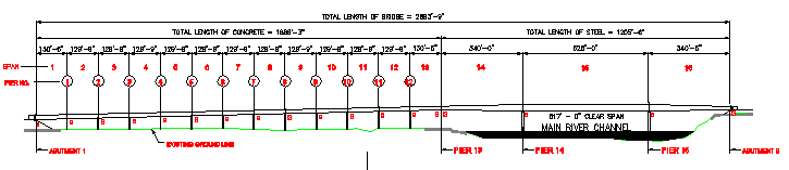
Figure 2-1 Elevation of State Route 69 bridge over the Tennessee River
Click within above figure to view a PDF plot of the drawing.
Wiss, Janney, Elstner Associates, Inc.
Collapse of the State Route 69 Bridge
over the Tennessee River at Clifton, Tennessee
for
Office of the Attorney General, State of Tennessee
WJE No. 951078
| 2.1 Description | ||
| Superstructure | Substructure | |
| Bridge Fabrication and Modifications | ||
| 2.2 Superstructure Erection Procedure | ||
The State Route 69 Bridge over the Tennessee River at Clifton, Tennessee (SR 69), was designed by the Structures Division of the Tennessee Department of Transportation (TDOT). Governing specifications for design included the Standard Road and Bridge Specifications of the Tennessee Department of Transportation (March 1981 Edition) and the AASHTO 1992 Standard Specifications for Highway Bridges with Addenda including the Standard specifications for Seismic Design of Highway Bridges.
The description that follows includes a brief review of both the concrete approach spans and the steel main spans. A more thorough discussion of modifications during fabrication and erection procedure are included for the collapsed structure.
The construction contract was let to McKinnon Bridge Company, Franklin, Tennessee, on September 10, 1993. McKinnon Bridge Company (MBC) constructed all the substructures, precast concrete girder approach spans, and bridge decks. Steel erection for the main 1,205-foot river crossing was subcontracted to ABC Contractors, Inc. (ABC), LaVergne, Tennessee. For this project, ABC supplied the ironworker crews and erection hand tools, while MBC provided the heavy lifting cranes, rigging, and equipment operators.
Structural steel fabrication was subcontracted by MBC to Trinity Industries, Inc. (TI). The steel was fabricated at their Mongomery, Alabama, facility. Shop drawings were prepared by Tensor Engineering Co., Satellite Beach, Florida. The Tennessee Department of Transportation retained the services of E. L. Conwell, Bridgeport, Pennsylvania, to observe the steel fabrication, monitor quality assurance procedures, and verify that Trinity Industries, Inc., performed the required testing and other checks during the fabrication process.
The SR69 Bridge includes 16 spans totaling 2,893 feet-9 inches in length. Spans 1 through 13 ( referred to as the approach spans) consist of prestressed, precast bulb-trees that span a total of 1,688 feet-3 inches. Spans 14 through 16, crossing the river, consist of three-span, continuous welded steel girders having a total length of 1,205 feet-6 inches. The vertical clearance of the steel structure above the river at normal pool elevation is 80 feet. An elevation of the bridge is shown in Figure 2-1. Note that Figs 2.1 through 2.10 are reproductions of details from drawings for the project with deletions and additions made for clarity.
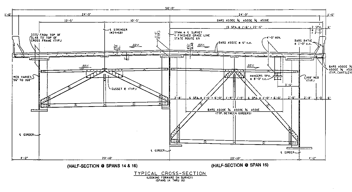
The 48-foot wide roadway was designed for three traffic lanes, but striping was for one traffic lane in each direction. Standard TDOT bridge rails were included. The concrete portion of the bridge has an upward grade of 1.6 percent followed by a 1,500-foot vertical curve in the steel structure. There are no horizontal curves in the bridge alignment. A typical cross-section through the concrete and steel bridges is shown in Figures 2-2 and 2-3.

Superstructure. The 13 approach spans are supported by six 72-inch deep prestressed, precast concrete bulb-tee girders with a span range of 129 feet-9 inches to 130 feet-6 inches. The bulb-tees are simply supported on elastomeric bearings with infill diaphragms cast to form fixed longitudinal connections to the piers. Two lines of intermediate steel angle cross frames are placed in each span between the bulb-tees girders. The general contractor elected to use precast, prestressed 3.5-inch bridge deck panels as stay-in-place formwork for the concrete deck. Total deck thickness was 8.25 inches. The bridge deck is designed with .25-inch/foot transverse cross slope for drainage.
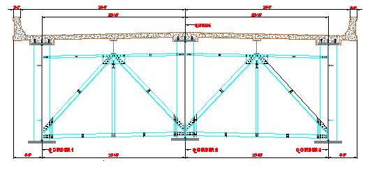
The three river-crossing spans are supported by three continuous girders spaced 20 feet-10 inches on center transversely and measuring 340 feet inches, 525 feet, and 340 feet-6 inches in length. Steel stringers, consisting of W24x60 members, are centered between the girders and supported by transverse cross frames. The cross frames are spaced at 24 foot-1.5 inch centers in the end spans and at 25-foot centers in the main span. Figure 2.4 shows a typical cross frame.

A system of W18x76 beams span diagonally between cross frames of adjacent girders. These diagonal members are attached to the bottom flanges of the girders. This lateral bracing extends about 200 feet into each end span from the river piers and throughout the center span.
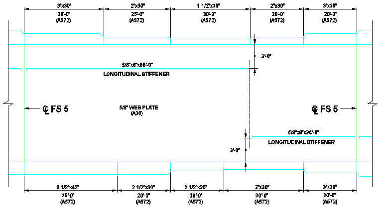
The three plate girders are identical in cross section. A diagram of a girder elevation showing the location, plate cross-section, and steel type used in fabrication is presented in Figure 2.5.
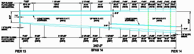
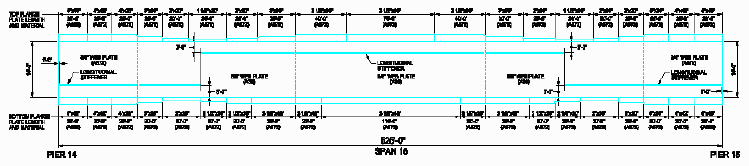
Girder depth is 8 feet at the ends (Pier 13 and Abutment 2) and increases to 14 feet at Piers 14 and 15; a constant 14-foot girder depth is maintained for the center span. Girder flange plates vary in cross-section from 1 inch thick by 30 inches wide to 4 inches thick by 48 inches wide. Changes in flange plate cross-section occur as often as every 20 feet. Web plate thicknesses are 1/2 inch, 5/8 inch, and 3/4 inch. The main span web plate measures 5/8 inches by 14 feet, except for 3/4 inch plate used over the river piers. Three grades of steel are specified for the girder fabrication: ASTM A709 (Bridge Grade A3), A572, and A852. In total, 4,480,000 pounds of structural steel is used in the superstructure. All field connections are bolted.
The girder web plates are fitted with vertical stiffeners connected by fillet welds. In the end spans, the stiffener spacing is typically 12 feet-0 3/4 inch Stiffener spacing in the main span is typically 12 feet-6 inches. The stiffener spacing varies slightly to accommodate bolted splice locations. The cross frames are connected to vertical stiffeners. These stiffeners are a 1-inch thick by 1 foot-2 inch wide full girder depth plate. The center girder has stiffeners on both sides of the web for the cross frame connections. Intermediate vertical stiffeners between cross frames consist of a 5/8 inch or 3/4 inch thick by 8-inch wide full girder depth plate located on one side of the web.
Composite action in positive moment regions of the bridge is provided by three lines of 7/8-inch diameter shear stud connectors. Grade 60 reinforcement (ASTM A615) is specified for the bridge deck.
Expansion joints separate the steel structure from the concrete approaches and from the abutment. Bearings at these joints consist of a pinned assembly mounted on self-lubricating sliding plates. The bearing devices at the main river piers are a pin and bearing assembly attached to a fixed plate.
Substructure. The SR69 approach and main spans are supported by 15 piers and two abutments constructed of reinforced concrete. Piers 1 through 13 supporting the precast concrete bulb-tee approach spans consist of a top hammerhead-shaped cross-beam supported by a pier shaft and footing. The cross-beams are typically 50 feet long, 7 feet-6 inches wide, and vary in depth from 5 feet at their ends to 11 feet-3 inches at the pier shaft centerline.
Nominal dimensions of the pier shaft are 12 feet by 6 feet. Pier 1 has a shaft height of 35 feet-9 inches, while Pier 13 has a 59 foot-7 inch shaft. Each shaft is supported by a 6-foot deep footing. Plan dimensions of the footing are 18 feet by 24 feet. The footing is typically reinforced with top and bottom mats of reinforcing bars. Vertical bars of the shaft extend into the footing. The footing is founded atop a grid of 48 HP12 x 63 steel piles driven vertically 40 to 80 feet to rock.
Piers 14 and 15 are located in the Tennessee River and are founded in rock below the river bottom. Each pier cross-beam is shaped like a hammerhead, 9 feet-6 inches wide, and varying in depth from 12 feet to 18 feet-3 inches. The overall beam length is 50 feet at the top and tapers out to a maximum length of approximately 55 feet-8 inches. The cross-beam, which supports the three girders, frames into a column shaft 8 feet wide by 20 feet long. For Pier 14, the shaft is approximately 86 feet tall, while Pier 15 has a shaft height of about 94 feet.
The shafts of both Piers 14 and 15 are founded on 5-foot deep reinforced concrete spread footings. In plan, the footings are 20 feet by 30 feet and contain top and bottom mats of reinforcing bars. As shown on Figure 2-6, the shaft and footing are integral elements.
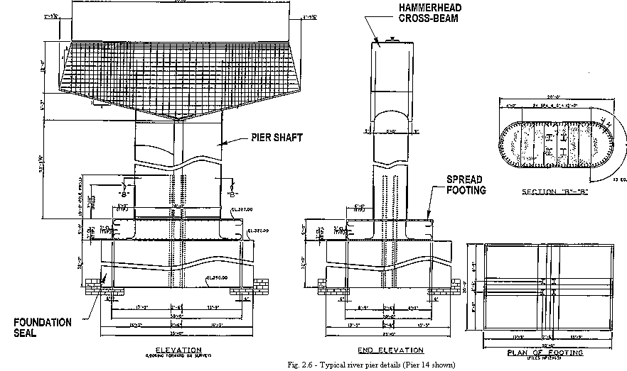
The spread footing sits on an unreinforced concrete seal cast into rock below the river bottom. The seal measures 29 feet by 35 feet in plan and has an approximate height of 32 feet at Pier 14 and 26 feet at Pier 15. The concrete seal provides support for the base of the steel sheet piling and seals the bottom of the cofferdam from water infiltration during construction of the pier. The seal concrete transfers pier loads to rock. Each seal contains four steel HP12 x 63 piles embedded full height in the seal and 15 feet into the spread footing and pier shaft.
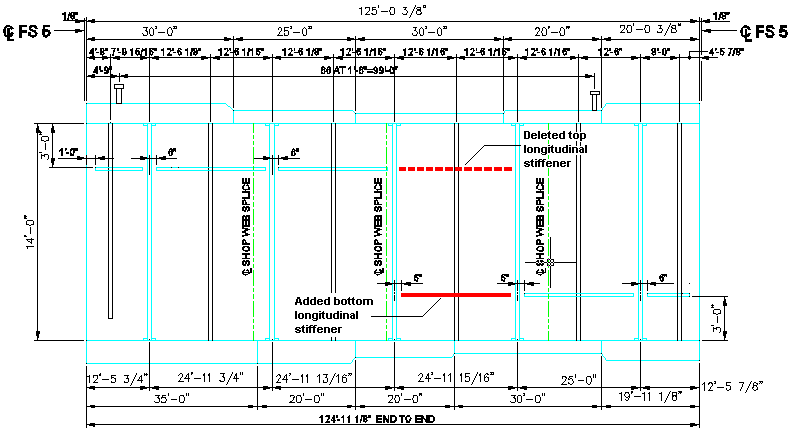
Bridge Fabrication and Modifications. For fabrication, piece numbers were assigned to the girder segments between the splice locations as depicted on the shop drawing plans shown in Figure 2-7, Figure 2-8, and Figure 2-9. The upstream (project north) fascia girder was labeled G1, the middle girder G2, and the downstream fascia girder G3. The individual girder segments between splices were lettered A through M.
During preparation of the shop drawings, Trinity Industries (TI) requested the addition of three bolted shop splices for each continuous girder located at each pier girder and at the center of the main span girder. Reportedly, this first modification was requested to aid with handling of the heavy deep girder segments at the TI facility. TDOT approved the additional bolted shop splices. As a result, Segments C and D were combined, as were Segments FG and JK. These splice locations are shown in Figures 2-7 through 2-9 above, with the designation SS1, SS2, and SS3. The additional weight added as a result of the shop splices totaled about 61,000 pounds per girder, or 183,000 pounds for the three girder superstructure. Since MBC could handle the heavy segments in the field, they had TI complete and paint the shop splices prior to shipping.
A second modification concerned the detailing of the girder bearing stiffeners located over the piers. The TDOT design drawings show the bearing stiffener connection to the bottom flange at Piers 13, 14, and 15, and Abutment No. 2 to be a full penetration, double bevel groove weld. Instead, the shop drawings show the stiffener detailed with no weldment to the bottom flange and the notation "GRIND TO BEAR." The shop drawings were approved by TDOT on March 1, 1994.
A third modification discovered during the removal operation was the shortening of a top longitudinal stiffener and the lengthening of the bottom longitudinal stiffener on the center span girders. The shop drawing reproduced in Figures 2-10a and 2-10b has been annotated to show the change in stiffener length from the design drawings.
The superstructure erection was carried out under the direction of the general contractor, McKinnon Bridge Company and its erection subcontractor, ABC Contractors, Inc. A general note on the design drawings prohibiting the use of temporary bents or falsework without permission of the U.S. Coast Guard was the only restriction on erection. Approval of the MBC erection scheme was given by the Construction Division of TDOT.
The McKinnon Bridge Company has constructed similar major steel structures for TDOT and over the years has built nearly 20 major bridges over the Tennessee River. The MBC fleet of high capacity, water-borne lifting cranes allows the construction of major bridges over navigable water without the use of falsework bents or towers.
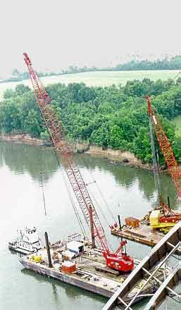
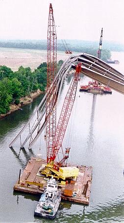
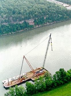
For this project MBC provided about 1,100 tons of lifting capacity using three water borne cranes. The cranes used to erect the bridge included two Manitowoc cranes and a derrick. One of the Manitowoc cranes, shown in Figure 2-11, was a track mounted Model 4100W Series 1 with a maximum-rated lift capacity of 200 tons. The second Manitowoc crane was a model 4100W Series 3 ringer, with a maximum lift capacity of 300 tons. Figure 2-12 shows the ringer crane. The third crane was reported to be a 600-ton capacity stiff-leg derrick purchased by MBC from Bristol Steel. The stiff-leg derrick is shown in Figure 2-13.
 |
 |
 |
| Figure 2-11 Manitowoc Model 4100W Series 1 crane with rated lifting capacity of 200 tons |
Figure 2-12 Manitowoc Model 400W Series 3 rigger crane with rated lifting capacity of 300 tons |
Figure 2-13 Stiff-leg Derrick with reported lifting capacity of 600 tons |
After fabrication, each girder segment was shipped by rail from Montgomery, Alabama, to the Tennessee River at Yellow Creek, Mississippi. The girders were then loaded on barges and floated to the construction site.
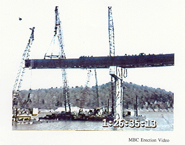
To erect a span, segments of girder lines G2 and G3 of varying length, consisting of all cross frames, lateral members and stringers, were assembled while on barges and then were lifted as a unit into position. In Figures 2-14a and 2-14b, the ringer crane and derrick are shown hoisting Segments F, G, & H of Girders G2 and G3 in place. While holding the free end with the derrick, the next unit was hoisted and connected.
 |
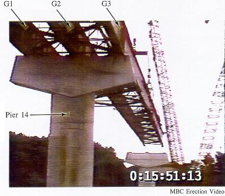 |
Figure 2-14a |
Figure 2-14b |
At the piers, each girder segment over the pier was lifted into place individually, as shown in Figure 2-15. Girder G1 was also erected individually in segments in the same manner as G2 and G3. About every fourth cross frame was connected during erection of G1.
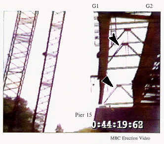
Cross frames were transported to the site with the top members folded down as depicted in Figure 2-9. The folded top members permitted the cross frames to be positioned easier during erection. Once the bottom and diagonal members were attached to a girder, the top member was rotated into position. Figure 2-16 shows two cross frames with top struts in the folded position before being attached to Girder G1.
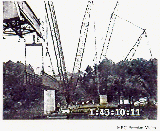
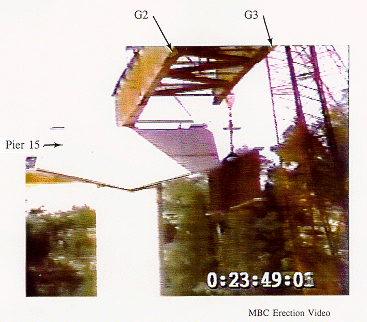
ABC began erecting the steel superstructure from Pier 13, progressing towards Abutment 2 on the east side of the river. Once Span 14 was completed, ABC cantilevered Segments E of all three girders 187 feet-6 inches passed Pier 14 as shown in Figure 2-17. Crane mats totaling about 60 tons were placed as counterweights in Span 14 to reduce the deflections of the cantilever. Girders G2 and G3 spanning the main river channel were erected before Girder G1. Figure 2-18 shows a partial view of the main span before completion Girder G1.
 |
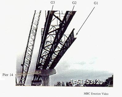 |
Figure 2-17 |
Figure 2-18 |
Back to page top
Back to WJE Report Chapter 1 or
To WJE Report Chapter 3
WJE Report Table of Contents