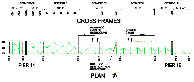
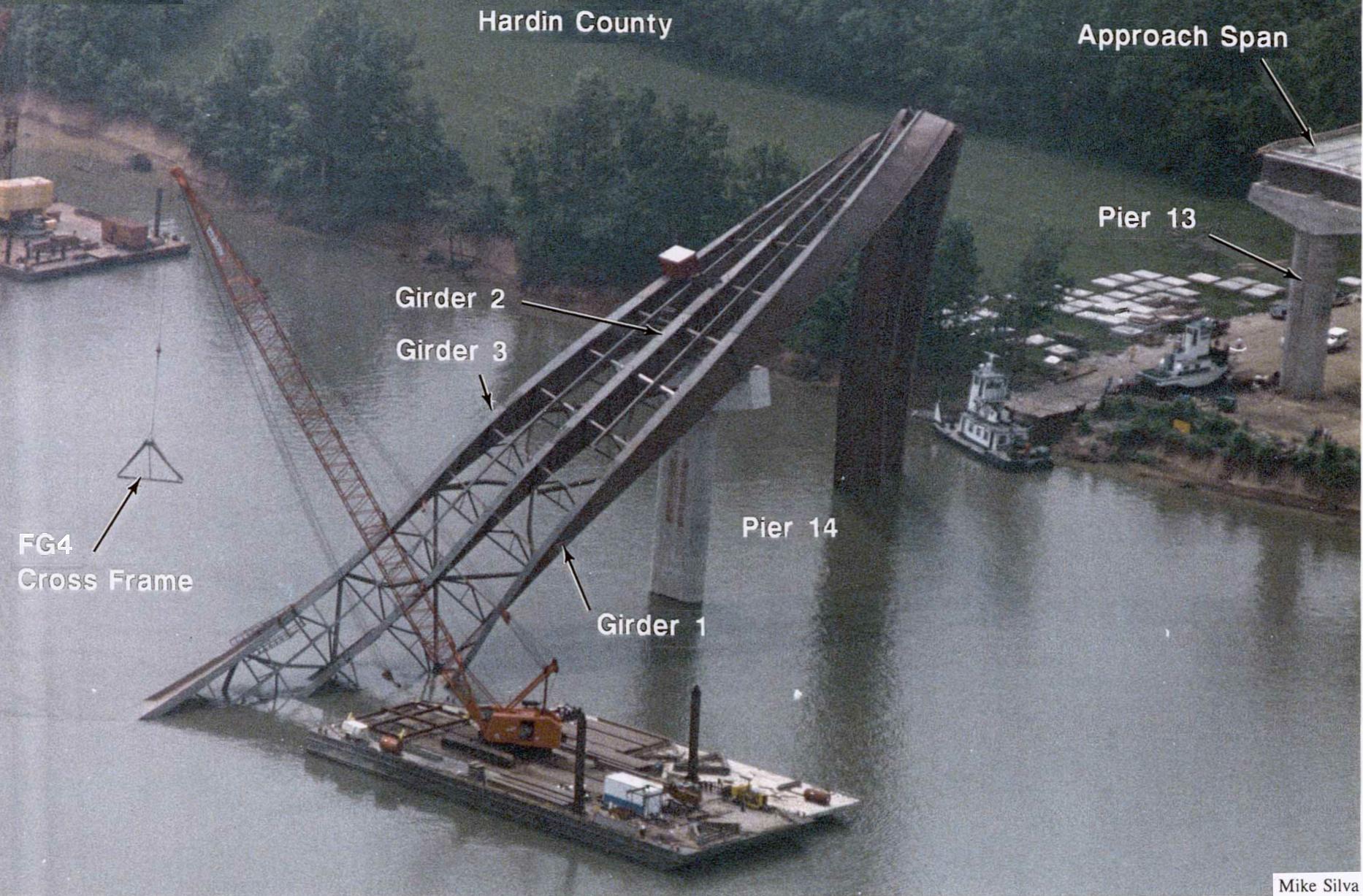
Fig. 3.3 - Contractor erection procedure on Friday, May 12, 1995 (AM)
Click inside image for a PDF plot of the engineering drawing of Fig. 3.3.
Wiss, Janney, Elstner Associates, Inc.
Collapse of the State Route 69 Bridge
over the Tennessee River at Clifton, Tennessee
for
Office of the Attorney General, State of Tennessee
WJE No. 951078
| Site Observations Prior to the Collapse Bridge erection status up to Thursday, May 11, 1995 Friday, May 12, 1995 Saturday, May 13 and Sunday, May 14, 1995 Monday, May 15, 1995 Friday, May 16, 1995 |
The State Route 69 bridge collapsed during erection on Tuesday, May 16, 1995 at about 9:45 a.m. A videotape record of the bridge taken about two hours before the collapse was obtained by the Attorney General's office. This tape provided visual confirmation of discussions and noted during the investigation. The following sections review the environmental conditions and the erection procedure prior to and around the time of collapse.
Work activities and their sequencing before the collapse that are addressed in the following paragraphs were obtained from discussions with several individuals. Descriptions from some individuals were not entirely clear and some accounts were inconsistent with one another. The information below represents WJE's understanding of the events that preceded the collapse.
Bridge erection status up to Thursday, May 11, 1995. As discussed in Section 2.2, units of Girders G2 and G3 were assembled on barges, lifted into position and held by a crane until the next unit was erected. At the piers, segments of G2 and G3 were erected individually. On March 2, 1995, Girders G2 and G3 were erected in Span 14, extending over Pier 14 into Span 15 by 62 ft-6 in. Segments of G1 were assembled and lifted in a similar manner. On March 14, 1995, Girder G1 was erected in Span 14, also extending past Pier 14. Three more girders were erected on March 30, 1995, terminating at Field Splice 4 (FS4) which was located 187 ft-6 in. from Pier 14. The erection of Girders G2 and G3 across the main span, Span 15, was performed on April 2, 1995.
By Thursday May 11, 1995, Girders G2 and G3 extended from Pier 13 to FS7, 60 ft-3 in. beyond Pier 15. All cross frames were installed and fully bolted. Field splices of the girders were completely bolted. The bottom flange lateral bracing was installed but not fully bolted. Girder G1 was erected from Pier 13 to 187 ft-6 in. into the main span, beyond Pier 14. The erected segments included A, B, combined segments CD, and E. Cross frames were fully bolted into position, all splice bolting was completed, and bottom flange lateral bracing was installed.
Friday, May 12, 1995. On Friday, the contractor continued erection of the main span of Girder G1. That morning, Segments FG and H were bolted together at FS5 while on a barge. As shown in Fig. 3.3, the length of these two segments was 275 ft. This piece was lifted into position with the ringer crane attached to Segment FG and the derrick hooked to Segment H. The approximate locations of the crane pick-up points are shown in Fig. 3.3
While being held in position by the cranes, FS4 between segments E and FG was assembled and partially bolted. In addition, the fourth and sixth cross frames (FG4 and FG6) from FS4 were installed in Segment FG and bolted with the aid of a cable hoist.
On Friday afternoon, when FS4 was considered to be sufficiently bolted, the ringer crane released Segment FG and moved into position to lift Segment JK into place over Pier 15. The derrick remained in position carrying the end of Segment H. During the erection of Segment JK, a significant outward lateral sweep was observed in the east end of Segment H of Girder G1. In an effort to correct the sweep condition, a cable hoist was attached between the bottom flange plates of Girders G1 and G2 and tightened. In addition, the Manitowoc 4100WS1 crane was hooked to the top flange near FS6. The load line of this crane was used to pull (overboom) the east end of Segment H towards Girder G2. Figure 3.4 shows the crane locations as Segment JK was connected to Segment H at FS6.
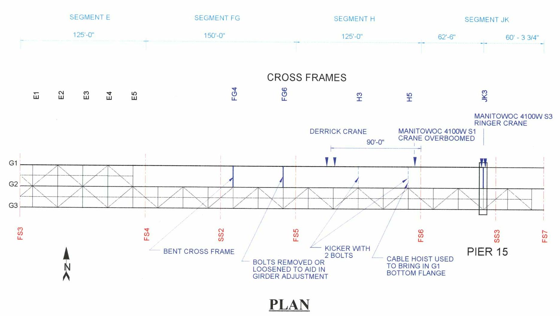
Prior to overbooming by the Manitowoc 4100WS1 crane or vertical adjustments by the derrick to aid in the fit-up of Girder G1 at Pier 15, connections of Cross Frame FG6 to Girder G2 were unbolted to allow transverse movement of the G1 girder to occur. However, the subsequent positioning of Girder G1, a double angle member of Cross Frame FG4 in Segment FG buckled.
Segment JK was moved into proper position, atop the Pier 15 bearing assembly, and FS6 partially bolted. Cross frame JK3 over Pier 15 was installed and a pair of steel kickers or horizontal struts were attached in Segment H as shown in Fig. 3.4 to properly space Girder G1 and temporarily brace the top flange. All cranes released their loads before work stoppage for the day.
Saturday, May 13 and Sunday May 14, 1995. The erector did not work over the weekend; therefore, the bridge remained in the same state of erection as on Friday evening. All crane and work barges were moored on the riverbanks so the channel was clear for commercial and recreational boat traffic.
Monday, May 15, 1995. On Monday, ABC Contractors began installing cross frames between Girders G1 and G2 using the Manitowoc 4100WS1 crane. Cross frame installation started at the cantilevered end of Segment JK and progressed toward the main span. As depicted in Fig. 3.5 cable hoists were used between Girders G1 and G2 to adjust to girder spacing. The hoists allowed the ironworkers to draw the two girders together to assist with cross frame connection bolting.
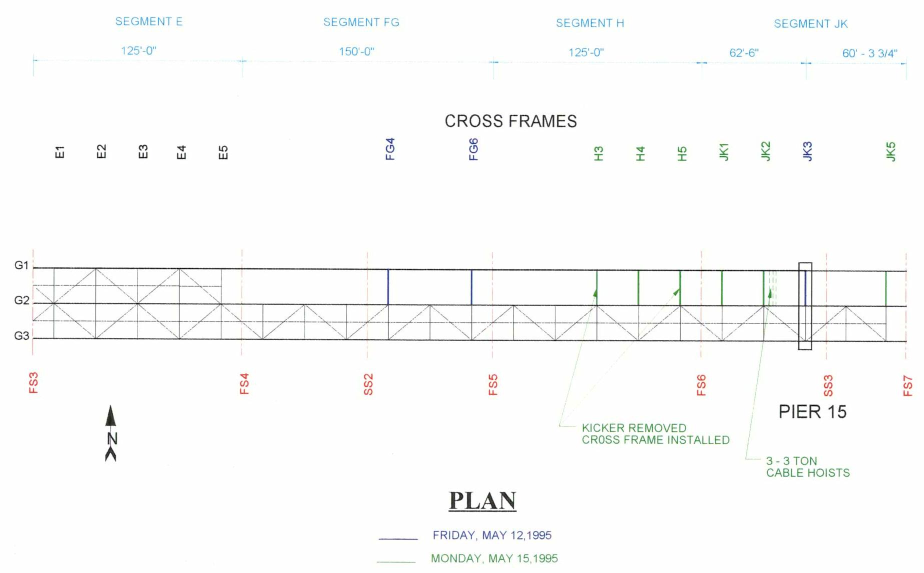
The end cross frame (JK5) adjacent to FS7 was reportedly the first unit installed on Monday. The next cross frame location was skipped because the cross frame was not at the site. Cross Frame JK3 at Pier 15 had been installed during erection of the pier girder. Cross frames were then installed at the remaining two Segment JK locations (JK1 and JK2).
Three consecutive cross frames (H5, H4, and H3) were then positioned and connected in Segment H. At two of the locations, temporary kickers between G1 and G2 were removed and replaced with permanent cross frames. The ironworkers noted significant misalignment of the bolt holes during fit-up of the cross frames. Several connections of these cross frames were only partially bolted. This completed the erection work on Monday.
Tuesday, May 16, 1995. On Tuesday, three ironworkers continued installation of cross frames between Girders G1 and 2. Two cross frames in Segment H (H1 and H2), and four of the six cross frames in Segment FG (FG1, FG2, FG3, FG5) remained to be installed.
The work progressed from Cross Frame H2 toward the FG segment. Again, the ironworkers had difficulty connecting Cross Frames H1 and H2 to Girder G1. The erector decided that a jacking beam needed to be fabricated to spread the top flanges of Girders G1 and G2 apart. While the jacking beam was being fabricated, Cross Frame FG5 was lifted into position and partially bolted between the two previously installed cross-frames. Figure 3.6 shows all cross frames installed prior to the collapse. Note that many of the cross frames, even though in place, were not fully bolted to the girders.
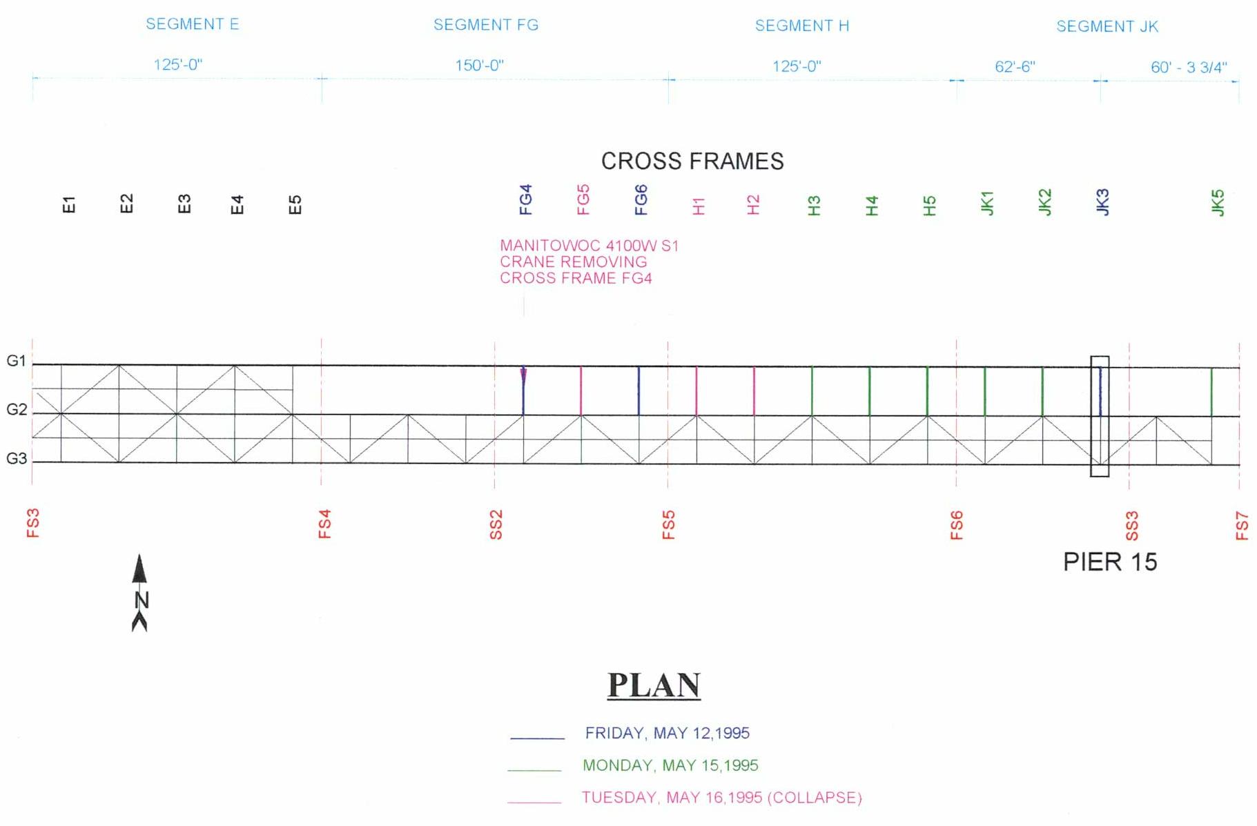
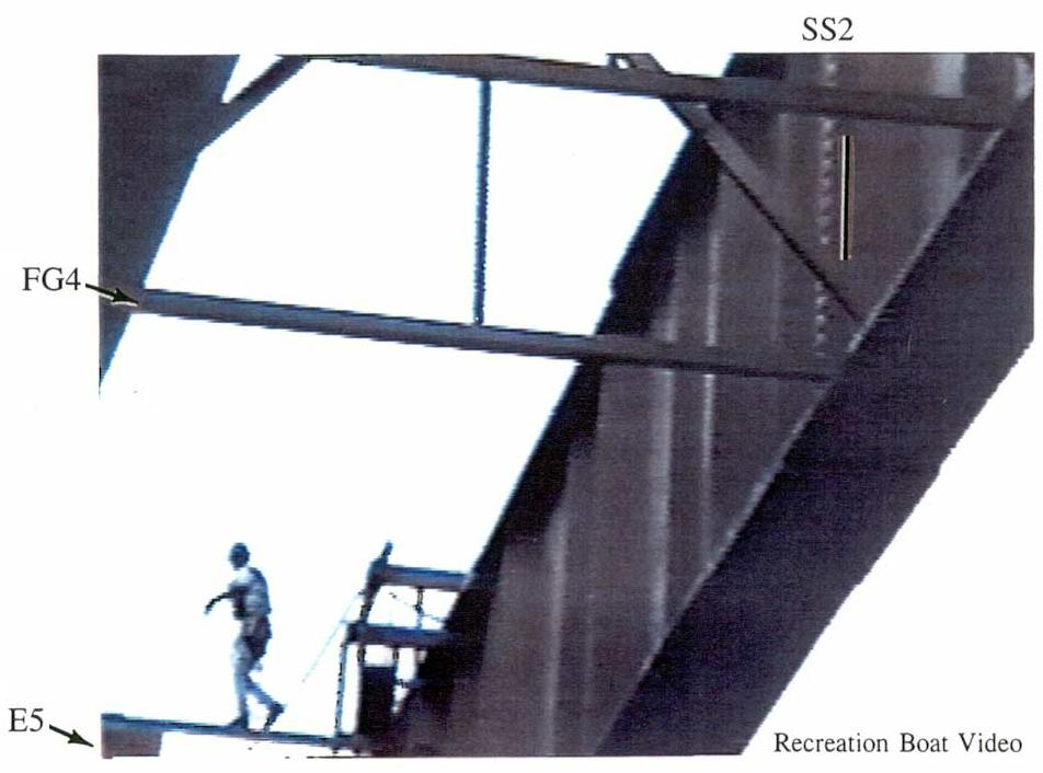
Once Cross Frame FG5 was set into position, but before the top horizontal members were bolted to the girders, ironworkers began removed the Cross Frame FG4 that was damaged sometime on Friday when the ironworkers were adjusting Girder G1 for placement on the bearing at Pier 15. Figure 3.7 is a close-up of two men next to a man in a basket on the top flange plate of SS2 at the center of the main span. The bucket on top of Girder G1, located to the east of the basket, is above the FG4 cross frame. Figure 3.8 shows a worker walking across the top strut of the last cross frame in Segment E (E5). No cross frames are installed between Cross Frame E5 and the buckled Cross Frame FG4.
|
|
|
Fig. 3.7- Close-up of man bucket with two men on Girder G1 at Shop Splice 2. Bucket east of basket over the forth cross frame (FG4) |
Fig. 3.8 - Ironworker walks across the top of E5. |
| Click inside either image to see a larger image. | |
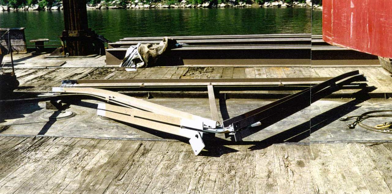
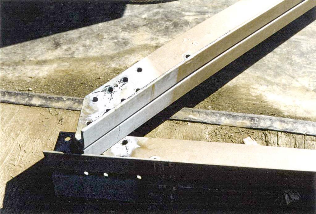
The bolts connecting Cross Frame FG4 to Girders G1 and G2 were either unbolted or torch-cut and removed. In addition the gusset bolts were removed to permit the top cross frame members to be lowered. Shortly thereafter, the erected superstructure collapsed. Cross Frame FG4 remained attached to the single part whip line of the Manitowoc 4100WS1 crane, as shown in Fig. 3.9. Subsequent examination verified that bolts had been unbolted or torch-cut and the top cross frame members lowered as shown in Fig. 3.10.
|
| Fig. 3.9 - Bridge site within hours of the collapse showing post-collapse conditions and Cross Frame FG4 hooked to the Manitowac 4100WS1 crane. Click inside image for a larger image. |
|
|
| Fig. 3.10a- Cross Frame FG4 Overall view of buckled cross frame with top struts lowered |
Fig. 3.10b - Cross Frame FG4 Cross frame bottom connection to Girder 2 showing markings from flame cutting used to remove bolts |
| Click inside either image to see a larger image in a new browser window | |
Back to page top
Back to WJE Report Chapter 2 or
To WJE Report Chapter 4
WJE Table of Contents