<==== Fig 4.1 (left)
Click inside either image
for a larger view
(600 pixel width)
in a new window.
Wiss, Janney, Elstner Associates, Inc.
Collapse of the State Route 69 Bridge
over the Tennessee River at Clifton, Tennessee
for
Office of the Attorney General, State of Tennessee
WJE No. 951078
After the collapse, rescue efforts were focused on recovering the missing ironworker from the river. On Wednesday, May 17, 1995, WJE engineers arrived at the site to examine the collapse. Portions of the steel superstructure not submerged in the river were sketched and photographed. River traffic was blocked until the body of the missing ironworker was recovered on Sunday, May 21.
|
|
| Fig. 4.2 (above) <==== Fig 4.1 (left) Click inside either image for a larger view (600 pixel width) in a new window. |
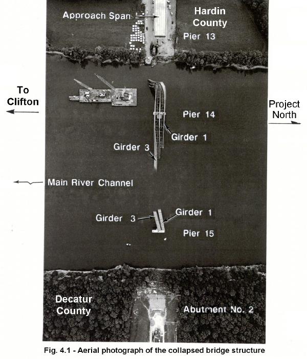
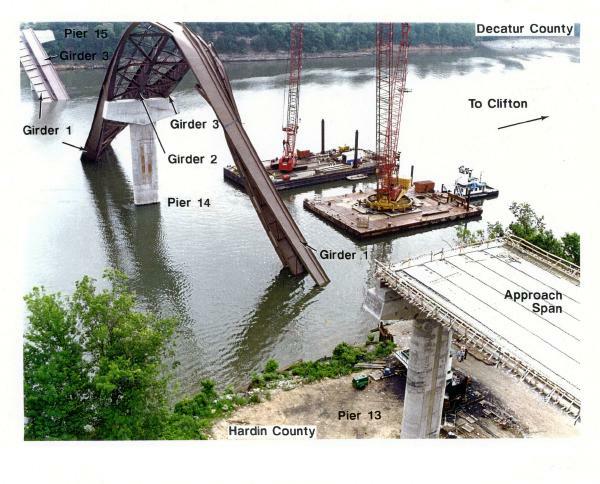
Site conditions. Figure 4.1 is an aerial photograph depicting the bridge site shortly after collapse. Figure 4.2 is another view of the collapsed bridge structure viewed from the west bank. As shown in the figures, the 525-foot span between Piers 14 and 15 fell into the main channel of the Tennessee River. Approximately, one-half of the main span was submerged below water. As the main span fell, the JK segments of all three girders were pulled longitudinally over the top of Pier 15 towards the main river channel. Approximately 100 feet of these segments remained exposed above water. On the Pier 14 side of the main span, longitudinal movement of the girders was apparently restrained by the shop splice flange plates which were bearing against the Pier 14 cross beam.
As shown in Figures 4.1 and 4.2, the three girders were elevated into the end span, Span 14, adjacent to Pier 14. At about 100 feet from Pier 14, all three girders were bent laterally, twisting and falling into the river. The bending occurred in the region of the girder cross-section with the 1-1/2 inch thick top and bottom flange plates. The girder ends, formerly bearing on Pier 13, were embedded into the river bottom adjacent to the west bank.
Site observations revealed the approach spans and Pier 13 were undamaged after the collapse. Pier 14 has a slight lean toward the main river channel, primarily attributed to the weight of the main channel girders eccentrically loading and pulling the pier top. Pier 15 appeared to be vertical, as originally built; the concrete cross-beam had small, minor spalls due to scraping of the girders.
Underwater examination of girders. On Monday, May 22, a diver with an underwater video camera began examining the submerged portions of the superstructure. The purpose of the underwater examination was to identify and record any possible failure locations or areas of concern before removal operations disturbed the collapsed members. The underwater inspection was concentrated between Piers 14 and 15, in water depths to 40 feet. All exposed girder bottom flange plates, except approximately 60 feet of the bottom flange of Girder G2 buried in the river bottom, were examined.
Cross frame connections to Girder G1 were examined to determine the locations of installed bolts. Due to the orientation of the G2 girder, many of the cross frame connections were not accessible.
Removal of superstructure. Based on the observations of the divers, a recovery plan was devised by the contractor to remove the superstructure from the river. Both river piers appeared to be structurally undamaged as a result of the collapse. River traffic was limited to single-width barges passing between Pier 15 and the east riverbank.
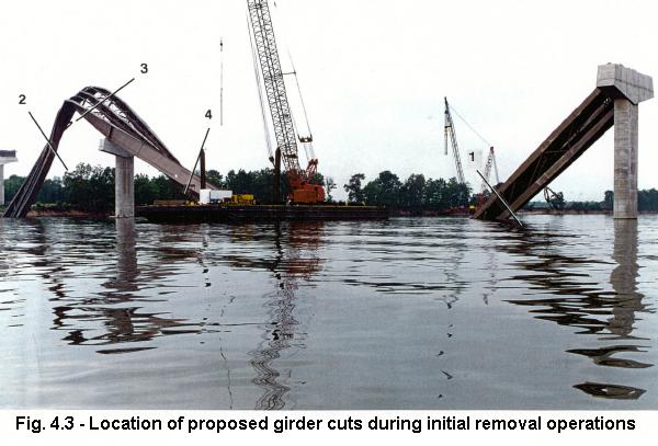 Fig. 4.3 - Location of proposed girder cuts during initial removal operations |
The proposed removal operations used linear explosive charges to cut the continuous girder segments into manageable pieces capable of being lifted. Flame or torch cutting of the steel was impractical because of the thick flange plates and potential danger of locked-in stresses while cutting. Figure 4.3 identifies the proposed cut locations initially planned by MBC. Demolition began near Pier 15 on May 26; however, the thick flange material at some cut locations required the use of custom-made explosive shape charges. The recovery plan was altered to begin removing steel from Span 14 while the new explosives were manufactured.
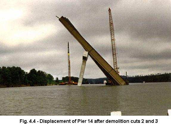 Fig. 4.4 - Displacement of Pier 14 after demolition cuts 2 and 3 |
After simultaneously making cuts 2 and 3, as shown in Figure 4.3, Pier 14 moved toward Pier 15 approximately 15 degrees from vertical. This noticeable displacement is shown in Figure 4.4. Underwater investigation of the pier showed separation between the footing and seal concrete. In late June, additional cuts were made in the steel superstructure using explosives, and the pier fell into the main river channel. Approximately 50 feet of Segment E of Girders G1, G2, and G3 were trapped under the pier.
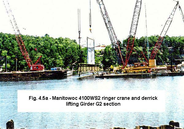
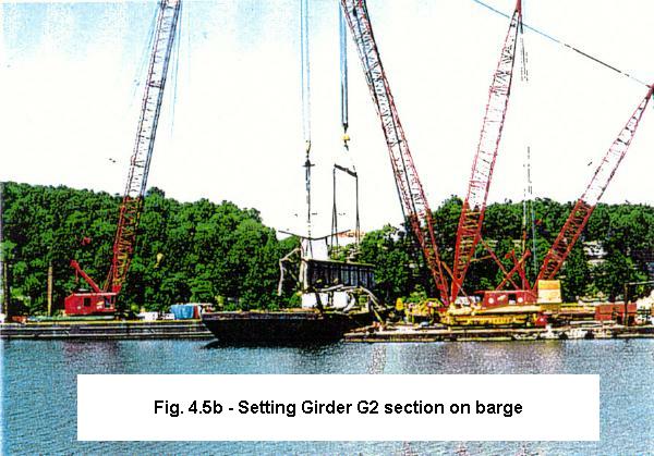
Removal efforts continued with underwater cuts being made to the submerged portions of the superstructure. Once cut, girder sections were hoisted by crane, placed on barges, and moved ashore. The west riverbank on both sides of the bridge alignment was cleared for storage of the removed pieces. Figures 4.5a, 4-5b, & 4-5c show some of the removal operations.
 |
 |
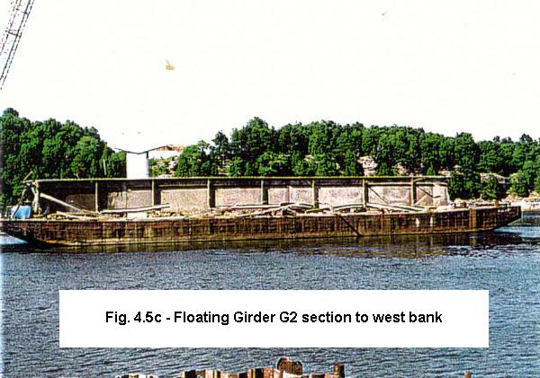 |
| Fig. 4.5a - Manitowoc 4100WS2 ringer crane and derrick lifting Girder G2 section | Fig. 4.5b - Setting Girder G2 section on barge | Fig. 4.5c - Floating Girder G2 section to west bank |
| Figures 4.5 - Views of girder removal operations Click inside any image for a larger view. |
||
On July 21, the final piece of Girder G1, Segment H, was lifted from the bottom. By late July, the main river channel was reopened for barge traffic. WJE concluded its field investigation on August 3. Demolition of Pier 14 continued through September. Several small pieces of girder from Segment E were removed as a result of the concrete demolition work. MBC began removing equipment from the site shortly after the superstructure was recovered. The last lifting crane was removed by the end of October concluding MBC's recovery work.
Test sample removal. On October 31 and November 1, 1995, selected steel samples were removed for material testing and metallographic examination. These samples were sent to Dr. John W. Fisher at Lehigh University. Structural components requested to be reserved for further examination will be removed at a later date and stored. This testing is discussed in Chapter 6.
 |
 |
| Fig. 4.6a | Fig. 4.6b |
| Figures 4.6 - Member identification scheme used to inventory the recovered steel Click inside either image for a larger view. |
|
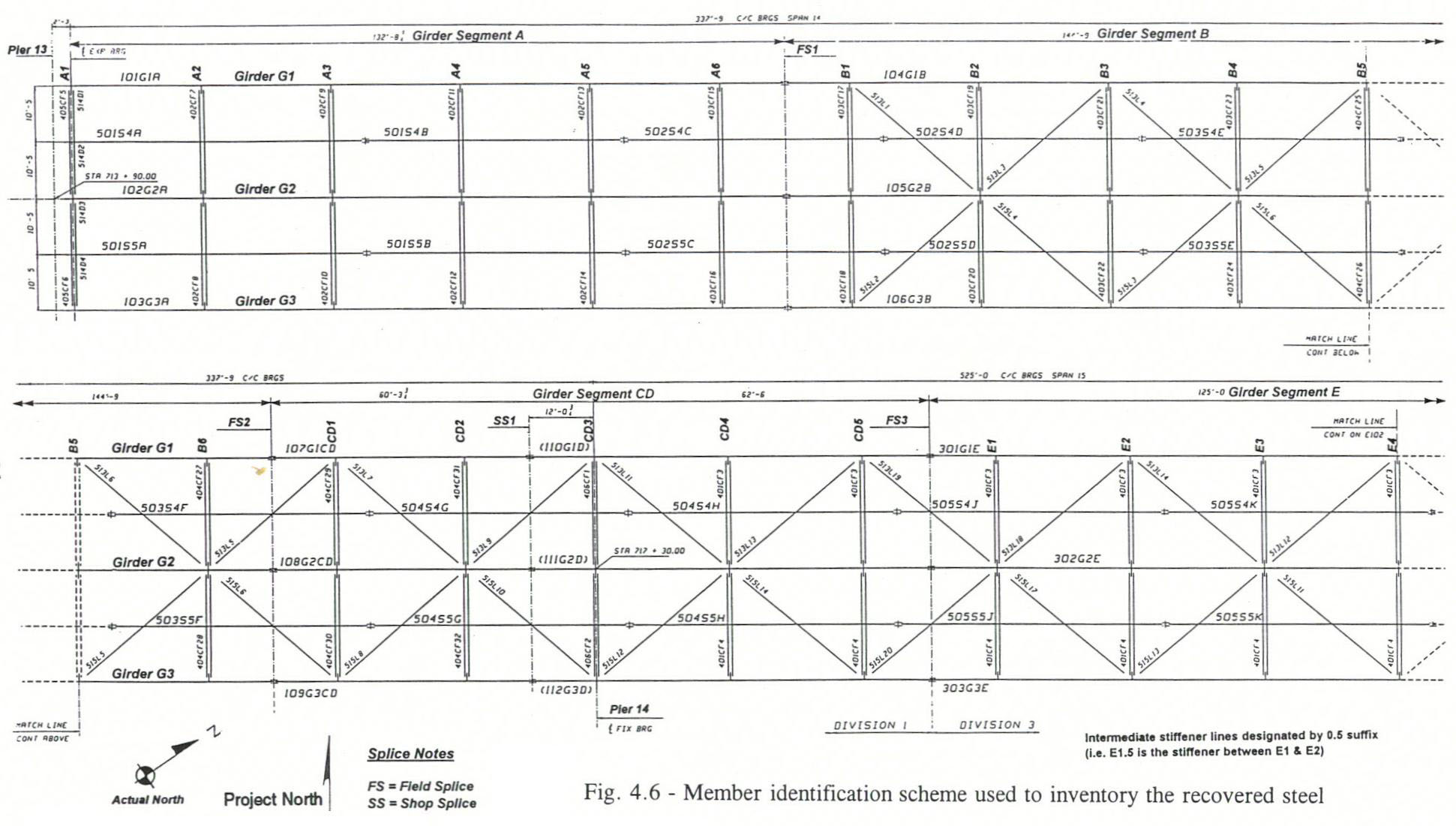
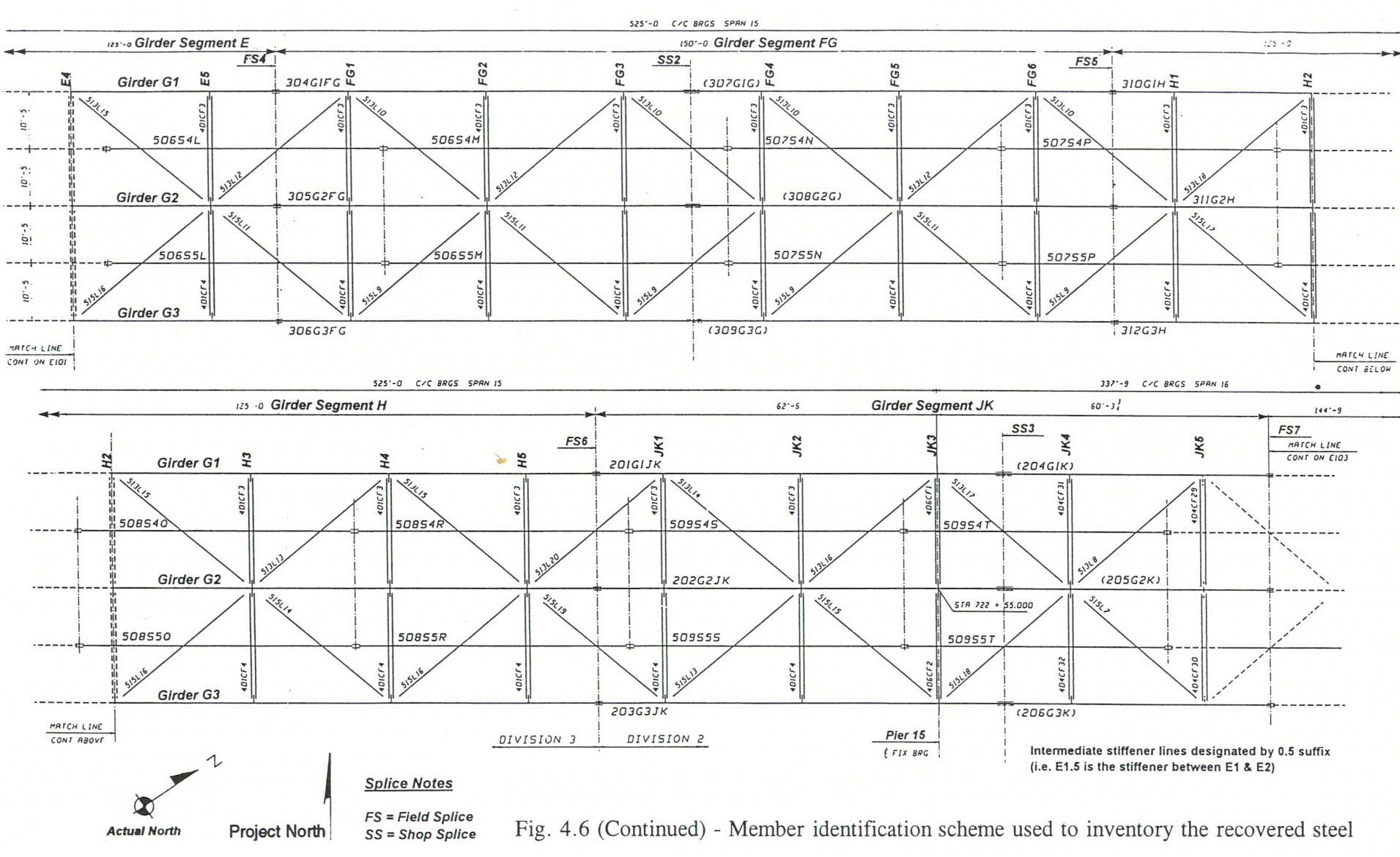
Identification. To document and inventory all removed steel, a member identification scheme based on the shop drawings was adopted. Figures 4.6a and 4.6b show the girder and cross frame identification system used. The girders kept the same shop drawing designation: G1, G2, and G3. The girder segments between field splices were identified as A, B, CD, E, FG, H, and JK. Cross frames within each girder segment were numerically identified starting from west to east (Pier 13 toward Pier 15) and carried the girder segment prefix. For example, Girder Segment CD had five lines of cross frames identified as CD1 through CD5. Field splices and shop splices were labeled FS and SS, respectively, with a numerical suffix that matched their shop drawing designation. Secondary members, such as individual bottom flange lateral bracing members or longitudinal stringers, were not specifically identified.
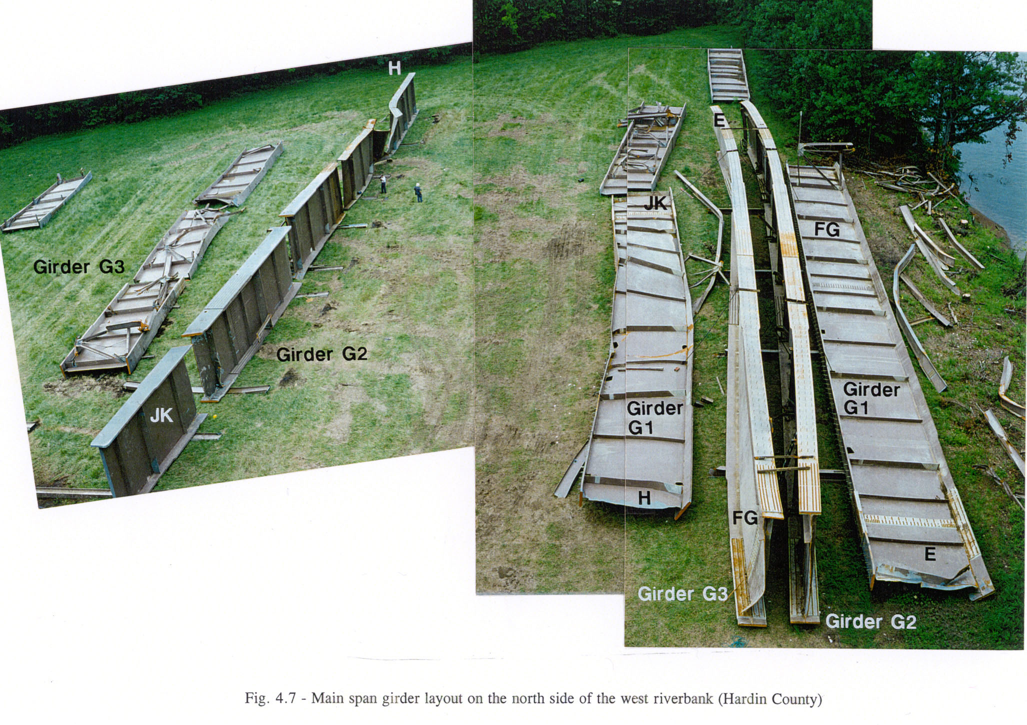
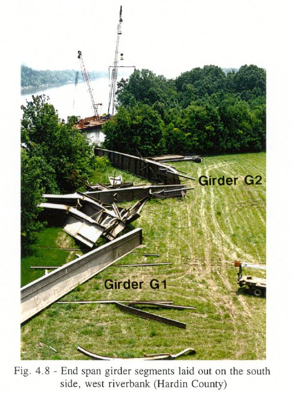
Steel sections recovered from the river were placed on the west riverbank. A crane was used to lay out the girders for detailed examination and review. Figure 4.7 shows the girders in Span 15 laid out for examination while looking north from the approach span. Figure 4.8 shows the girder segments in Span 14, looking south. Typically, splices, cross frames, intermediate cross frame stiffeners, and pier locations for each girder segment were identified. A summary of the girder pieces recovered and removal order is contained in Table 4.1.
 |
 |
| Fig. 4.7 - Main span girder layout on the north side of the west riverbank (Hardin County) (2054 x 1450 image size) Click here for a 600 x 379 image of Fig. 4.7 (suitable for printing). |
Fig. 4.8 - End span girder segments laid out on the south side, west riverbank (Hardin County) |
| Click inside either image for a larger view. | |
| Girder Piece (1) | Date Recovered | Notes |
|---|---|---|
| Girder G1 | ||
| A1 to B1(+)(2) | June 7, 1995 | includes FS1 |
| B2(-) to B4(+) | June 5, 1995 | lifted with G2 and G3 |
| B5(-) to CD5(+) | June 9, 1995 | includes FS2, SS1, and FS3 |
| E1 to E3 | not recovered | under Pier 14 |
| E3(+) to E4(+) | late July | -- |
| E5(-) to FG6(+) | June 20, 1995 | includes FS4, SS2, and FS5 |
| H1(-1) to JK1 | June 21, 1995 | includes FS6 |
| JK1(+) to JK5(+) | June 8, 1995 | includes SS3; ends at FS7 |
| Girder G2 | ||
| A1 to B1(+) | June 7, 1995 | includes FS1 |
| B2(-) to B4(+) | June 5, 1995 | lifted with G1 and G3 |
| B5(-) to CD5(-) | June 24, 1995 | includes FS2 and SS1 |
| CD5(-) to E3(-) | not recovered | under Pier 14 |
| E3(-) to E4(-) | late August | -- |
| E4 to FG6(+) | July 18, 1995 | includes FS4, SS2, FS5 |
| H1(-) to H3 | June 30, 1995 | -- |
| H3(+) to JK2 | June 6, 1995 | includes FS6 |
| JK3(-) to JK4(+) | July 7, 1995 | includes SS3 |
| JK4(+) to JK5(+) | July 7, 1995 | ends at FS7 |
| Girder G3 | ||
| A1 to B1(+) | June 8, 1995 | includes FS1 |
| B2(-) to B4(+) | June 5, 1995 | lifted with G1 and G2 |
| B5(-) to CD5(+) | July 11, 1995 | includes FS2, SS1, and FS3 |
| E1(-) to E3(-) | not recovered | under Pier 14 |
| E3(-) to E4(+) | late August | -- |
| E4(+) to FG6(+) | July 13, 1995 | includes FS4, SS2, FS5 |
| H1(-) to H3(+) | June 30, 1995 | -- |
| H3(+) to H5(+) | June 30, 1995 | -- |
| H5(+) to JK2(+) | June 30, 1995 | includes FS6 |
| JK2(+) to JK5(+) | July 8, 1995 | includes SS3; ends at FS7 |
| Notes: | (1) Refer to Figures 4.6a and
4.6b for girder and stiffener line identifications (2)A minus (-) sign indicates left or west of stiffener A plus (+) sign indicates right or east of stiffener |
|---|
Once identified, each piece of steel was examined for noticeable deformations, fractures, weld distress, and other pre- or post-collapse damage. Documentation was accomplished with measurements, sketches, and written notes of various conditions supplemented with photographs. The following sections summarize the examination of the girders and cross frames.
Girder conditions. Examination of the girder sections revealed damage primarily due to the collapse. Additional damage caused by the cutting, lifting and handling during recovery was also observed.
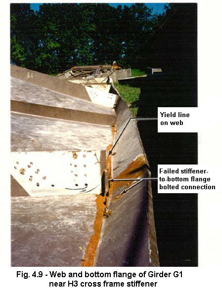
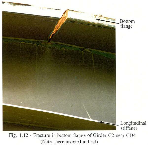
Three pieces were recovered from the main span of Girder G1. One piece included the entire Segment FG with FS4 and FS5, and a small piece of Segment E incorporating the E5 cross frame stiffener. A second piece consisted of Segment H, FS6, and Segment JIK to just beyond the JK1 cross frame stiffener. The last piece contained the E4 cross frame stiffener of Segment E.
 |
 |
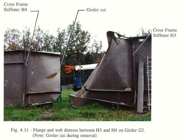 |
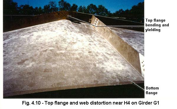
| Fig. 4.9 - Web and bottom flange of Girder G1 near H3 cross frame stiffener | Fig. 4.10 - Top flange and web distortion near H4 on Girder G1 | Fig. 4.11 - Flange and web distress between H3 and H4 on Girder G2 (Note: Girder cut during removal) |
 |
 |
| Fig. 4.12 - Fracture in bottom flange of Girder G1 near CD4 (Note: piece inverted in field) |
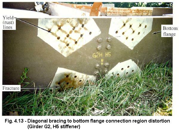
Fig. 4.13 - Diagonal bracing to bottom flange connection region distortion (Girder G2, H5 stiffener) |
Cross frame connections. The number of cross frames installed and their manner of failure (if any) was investigated. Each cross frame stiffener and corresponding cross frame, if found, were closely examined. The criteria listed below were developed to determine if the cross frame was fully or partially bolted prior to the collapse.
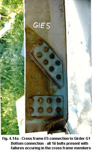
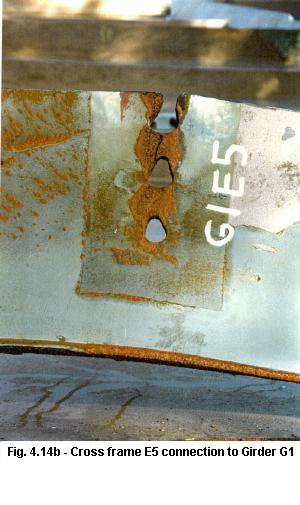
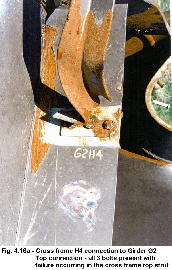
From the examination of the girder pieces, it was found that all cross frames were installed between Girders G2 and G3 for the full length of the erected steel. Cross frames were also installed between Girders G1 and G2 from Segments A through E. It is evident from Figures 4.14a and 4.14b that all 19 bolts (3 top and 16 bottom) were installed in the E5 cross frame stiffener to Girder G1 connection. Fully bolted bottom connections typically failed as shown in Figure 4.14a with the cross frame double angle members fracturing at the first bolt location. Fully bolted top connections typically failed with either the bolt holes undergoing extensive plowing or elongation as shown in Figure 4.14b, or by fracture of the top members through a bolt hole as shown in Figure 4.16a. Bent cross frame stiffeners were another indication that cross frame connections were fully bolted. As cross frame angles buckled, the stiffener in the vicinity of the connection was bent as is shown in Figure 4.15.
 |
 |
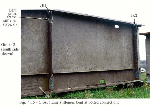 |
| Fig. 4.14 - Cross frame E5 connection to Girder G1 | Fig. 4.15 - Cross frame stiffeners bent at bolted connections |
|
|---|---|---|
| Fig. 4.14a - Bottom connection - all 16 bolts present with failures occurring in the cross frame members | Fig. 4.14b - Top connection - all 3 bolts severely distorted and elongated the holes | |
 |
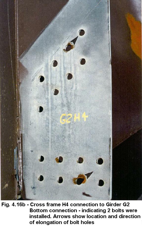 |
| Fig. 4.16 - Cross frame H4 connection to Girder G2 | |
|---|---|
| Fig. 4.16a - Top connection - all 3 bolts present with failure occurring in the cross frame top strut | Fig. 4.16b - Bottom connection - indicating 2 bolts were installed. Arrows show location and direction of elongation of bolt holes |
Bolts also fractured or pulled through partially bolted connections. As shown in Figures 4.16a and 4.16b, the Cross Frame H4 to Girder G2 connection had 3 bolts installed at the top connection to the stiffener, causing fracture of the cross frame member. The bottom connection had only 2 out of 16 bolts installed, and failure occurred in the bolts. Prior to bolt fracture, elongation of the holes occurred due to the bolt shank bearing on the stiffener plate.
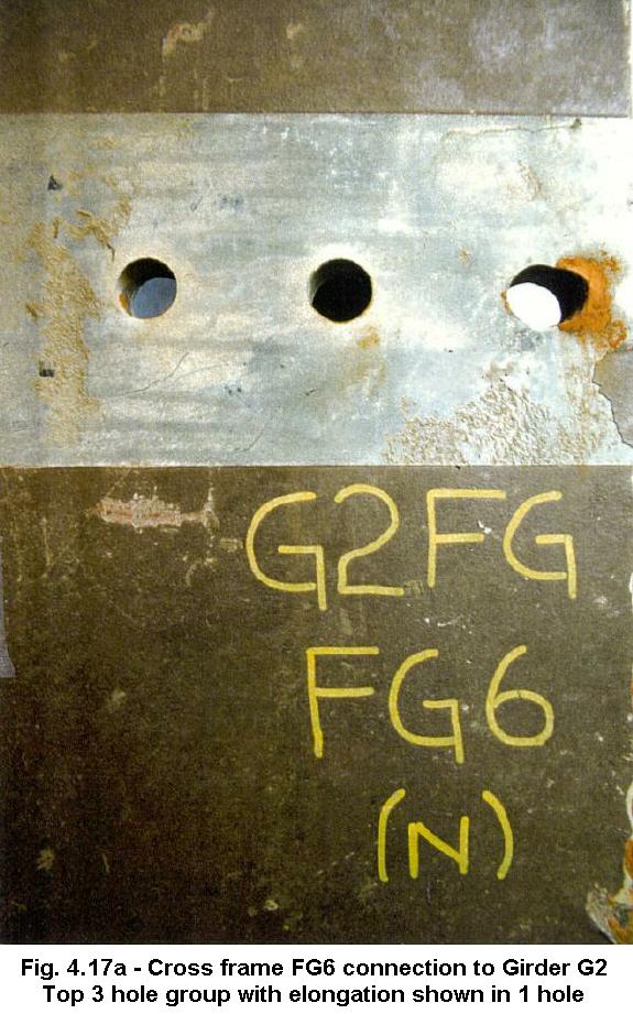
Typical hole elongation from a bolt is shown in Figures 4.17 and 4.17b for one top cross frame stiffener at FG6 for Girder G2. As is shown for this three-bolt connection, only one bolt was installed.
 |
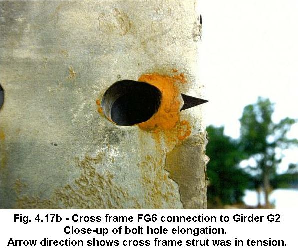 |
| Fig. 4.17 - Cross frame FG6 connection to Girder G2 | |
|---|---|
| Fig. 4.17a - Top 3 hole group with elongation shown in 1 hole | Fig. 4.17b - Close-up
of bolt hole elongation. Arrow direction shows cross frame strut was in tension. |
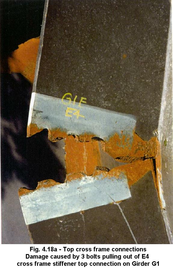
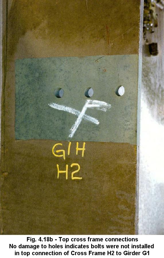
Figures 4.18a and 4.18b also show cross frame top connections to stiffeners and E4 and H2 with 3 bolts and 0 bolts, respectively.
 |
 |
| Fig. 4.18 - Top cross frame connections | |
|---|---|
| Fig. 4.18a - Damage caused by 3 bolts pulling out of E4 cross frame stiffener top connection on Girder G1 | Fig. 4.18b - No damage to holes indicates bolts were not installed in top connection of Cross Frame H2 to Girder G1 |
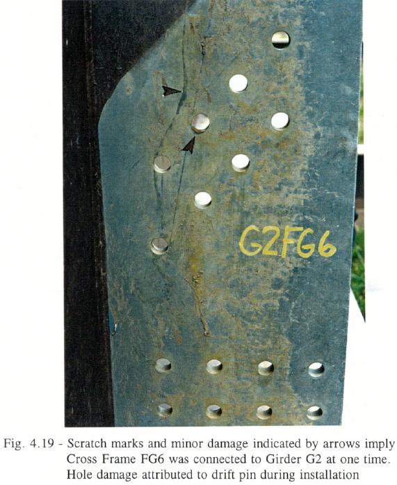 |
| Fig. 4.19 - Scratch marks and minor damage indicated by arrows imply Cross Frame FG6 was connected to Girder G2 at one time. Hole damage attributed to drift pin during installation |
Another condition observed was the presence of minor hole damage and scratch marks along a cross frame stiffener, as shown in Figure 4.19. This indicates that Cross Frame FG6 was connected to Girder G2 at one time; however, the absence of hole elongation required to fracture or pull out a bolt suggests no bolts were in the connection at the time of collapse. Instead, the minor hole damage was likely caused by a drift pin used to align the connection during installation. This minor distortion or abrasion was observed at numerous connection locations.
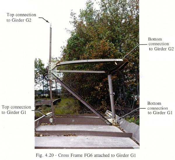 |
| Fig. 4.20 - Cross Frame FG6 attached to Girder G1 |
ABC mentioned that Cross Frame FG6 was unbolted to aid in adjustment of Girder G1 at Pier 15. The condition of Cross Frame FG6, shown in Figure 4.20, was observed closely. This figure shows the lower double angle member bent laterally in the middle and the companion diagonal member bent downward and laterally at the top gusset plate. The remaining angles were not significantly bent or twisted. Cross Frame FG6 was the only attached cross frame recovered east of FS4 with unbent top struts. As discussed above, only one bolt was found in the top connection and no bolts were found in the bottom connection to Girder G2. Only one bolt appeared to have been installed in the top connection to Girder G1. The lower connection to Girder G1 had 8 bolts installed; 5 were present and 3 had fractured. Further observation revealed the web of Girder G1 adjacent to the top connection was indented and the paint was scraped.
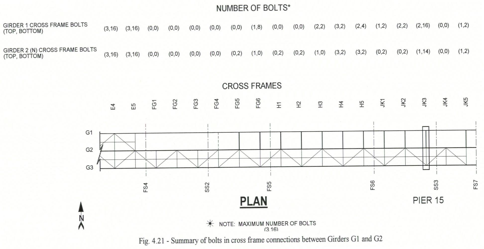
Based on the discussed criteria, recovered members, comments from ABC workers, and views of the bridge during erection and from a recreation boat video taken the morning of the collapse, an accurate condition of all cross frames was obtained. Figure 4.21 shows a plan view of the bridge from Cross Frame E4 to Cross Frame JK5. The number of bolts connecting the cross frames to Girders G1 and G2 is shown in the parentheses above the plan. The first number in the parentheses is the estimate of the number of bolts installed in the top connection, which is three when completed. The second is the number of bolts in the bottom connection out of a total of 16 when completed. Cross frames not shown on the plan were not installed.
 |
| Fig. 4.21 - Summary of bolts in cross frame connections between Girders G1 and G2 |
As discussed in Section 3.3, the ironworkers had difficulty installing the cross frames. Cross Frames JKI4, JIK2, JK1, H5, H4, and H3 were only partially bolted during erection on Monday, May 15. On Tuesday, May 16, it is apparent that Cross Frames H2, H1, and FG5 were installed with only two bolts in the bottom connection to Girder G2 and no top or bottom connections made with Girder G1.
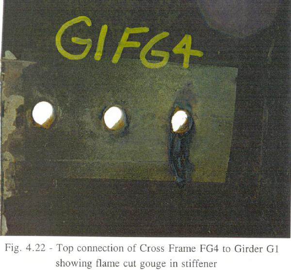 |
| Fig. 4.22 - Top connection of Cross Frame FG4 to Girder G1 showing flame cut gouge in stiffener |
Cross Frame FG4 is identified as having no bolts in any connection at either the G1 or G2 girders. As clearly shown in Figure 1.3 and Figure 3.9, this cross frame was suspended from the Manitowoc 4100WS1 crane at the time of collapse. Earlier, the bolts had been torch cut or unbolted for disconnecting the cross frame from the stiffeners. The condition of the holes for the top connection to Girder G1 is shown in Figure 4.22.
MBC and ABC reported concerns about fit-up problems to TI, the steel fabricator for the superstructure. These items included the cross frame to stiffener connection bolt groups, alignment of Girder G1 near Pier 15, a dimensional problem with Girder G2, and hold placement for bolted splices. MBC and ABC indicated that fit-up and bolt-up problems made the erection of this steel superstructure more difficult than other similar bridges they have constructed.
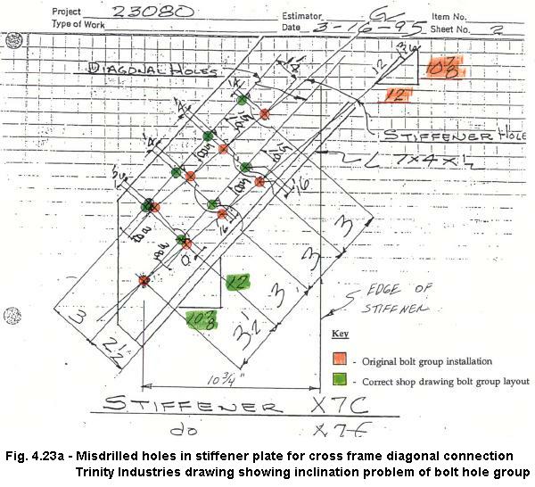
Cross frame to stiffener connection. On March 15, 1995, TI advised MBC that some cross frame stiffener drilling templates were made incorrectly for the eight bolt group of the cross frame diagonal connection. In total, 12 girder segments had misdrilled bolt hole patterns. At that time, two girder segments were already erected, three were on the job in barges, and seven were at TI. Trinity Industries, through MBC, are requested a corrective retrofit that consisted of drilling a new bolt hole pattern through the existing cross frame stiffeners at the correct inclination. Figure 4.23a is a TI drawing of a common cross frame stiffener showing both the incorrectly drilled holes and the correct hole pattern. Note that the slope of the diagonal bolt group was drilled at a 10-7/8:12 slope; while the shop drawing specified a 12:10-7/8 slope. The new bolt hole pattern used the lowest hole in this group as a common hole and rotated the new group around this hole to obtain the proper slope. This modification detail resulted in overlapping holes near the common hole and two holes about 1-1/4 inches apart at the furtherest hole from the common hole.
 |
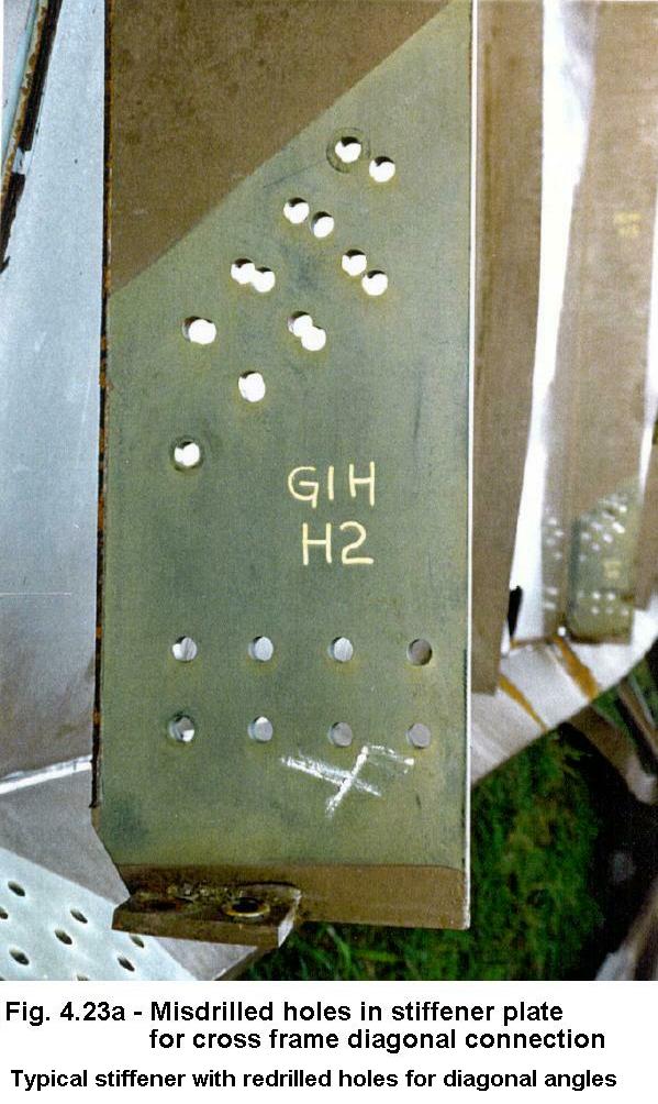 |
MBC forwarded the TI drawings to TDOT for review and approval of the corrective measure. TDOT approved drilling the new hole pattern in the cross frame stiffeners at the correct layout. A typical redrilled cross frame stiffener plate is shown in Figure 4.23b.
Fig. 4.23b - Misdrilled holes in stiffener plate
for cross frame diagonal connection
Typical stiffener with redrilled holes
for diagonal angles
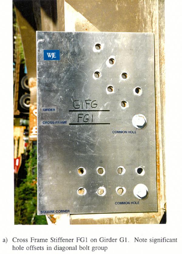
Another problem noted at a few cross frame stiffener locations was hole position within a bolt group. During the underwater examination, two cross frame angle to stiffener connections were observed connected with a few bolts while adjacent holes in that group exhibited significant offsets making bolt-up difficult. Examples of the hole layout problem within a bolt group are shown in Figures 4.24a and 4-24b. For this check, a template was fabricated to the shop drawing layout and positioned over the bottom bolt group of a cross frame connection using two bolts in the common holes for alignment. Figure 4.24a shows significant offsets for the seven holes of the diagonal connection. Many holes in this group are offset by as much as 1/4 the hole diameter. The diagonal bolt group shown in Figure 4.24b indicates misalignment approaching 1/2 the hole diameter. Bolt fit-up would be impossible without reaming or redrilling.
 |
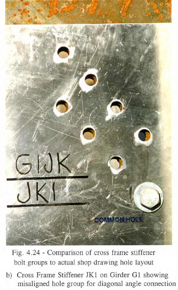 |
| Fig. 4.24 - Comparison of cross frame stiffener bolt groups to actual shop drawing hole layout |
|
|---|---|
| Fig. 4.24a - Cross Frame Stiffener FG1 on Girder G1. Note significant hole offsets in diagonal bolt group | Fig. 4.24b - Cross Frame Stiffener JK1 to Girder G1 showing misaligned hole group for diagonal angle connection |
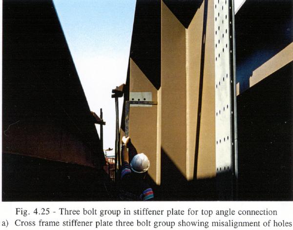
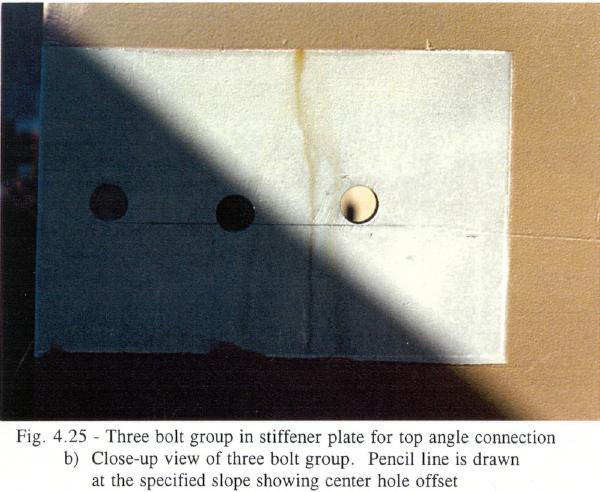
Figure 4.25a shows a cross frame stiffener with a three bolt group for connection of a top cross frame member. Inclination of this bolt group is given on the shop drawings as 1/4:12. The proper alignment is shown by the pencil line in Figure 4.25b. Note that the center hole of this three bolt group is about 1/4 inch lower than the correct location.
 |
 |
| Fig. 4.25 - Three bolt group in stiffener plate for top angle connection | |
|---|---|
| Fig. 4.25a - Cross frame stiffener plate three bolt group showing misalignment of holes | Fig. 4.25b - Close-up view of three bolt group. Pencil line is drawn at the specified slope showing center hole offset |
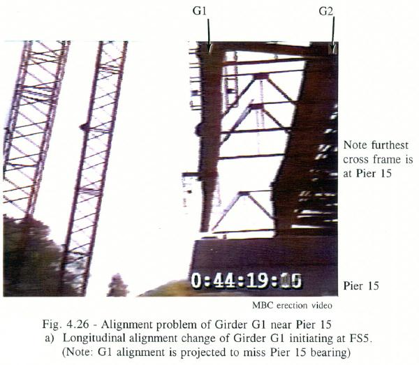
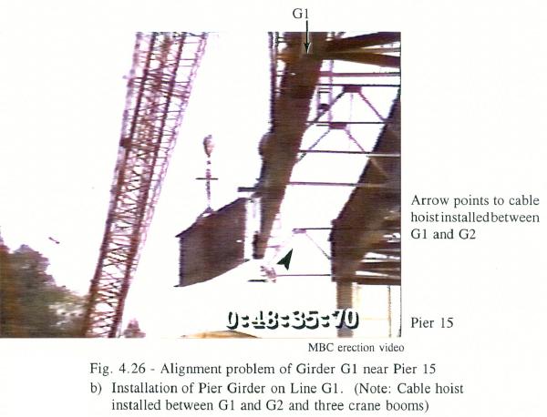
Alignment of Girder G1 near Pier 15. It was indicated by the erector that an alignment problem occurred in the 525 foot main span of Girder G1 near Pier 15. Specifically, it was noted that Girder G1 (Segment H) changed longitudinal alignment at FS5 toward Pier 15. This change in alignment, if projected to Pier 15, would result in a significant lateral offset between Girder G1 and the bearing. This alignment change is shown in Figure 4.26a. Prior to installing the pier girder segment, the erector adjusted the alignment of Girder G1 between FS5 and FS6 by installing a cable hoist near FS6 on the bottom flange to pull Girder G1 toward G2. In addition, the erector attached the Manitowoc 4100WS1 crane to the top flange of Girder G1 near FS6 and overboomed the load line to assist in pulling Girder G1 toward G2. The rigging used to adjust the girder alignment is shown in Figure 4.26b. The photographs shown in Figure 4.26 were reproduced from a video taken by the erector on May 12, 1995.
 |
 |
| Fig. 4.26 - Alignment problem of Girder G1 near Pier 15 | |
|---|---|
| Fig. 4.26a - Longitudinal alignment change of Girder G1 initiating at FS5. (Note: G1 alignment is projected to miss Pier 15 bearing) | Fig. 4.26b - Installation of Pier Girder on Line G1 (Note: Cable hoist installed between G1 and G2 and three crane booms) |
Top flange plate length Girder G2. The erector mentioned that, while connecting Girders G2 and G3 together on barges, Segment FG (from FS4 to FS5) of Girder G2 was found to be 2 inches shorter in length than the corresponding section of Girder G3. In addition, the erector believed that this segment of Girder G2 exhibited less camber than Girder G3. After erection, this discrepancy was reportedly observed at the bearing location at Pier 15.
Once the main span girders were recovered from the river, flange plate lengths were measured between FS5 and SS2, and SS2 and FS5. Field measurements and shop drawing dimensions are summarized below:
| Flange Plate Length (feet - inches) | ||||
|---|---|---|---|---|
| Girder No. |
FS4 to SS2 | SS2 to FS5 | Total From FS4 to FS5 |
|
| Top Flange Plate | ||||
| G1 | 75 - 0 | 74 - 11 3/4 | 149 - 11 3/4 | |
| G2 | 74 - 11 | 74 - 11 | 149 - 10 | |
| G3 | 75 - 0 | 75 - 0 | 150 - 0 | |
| Shop Drawings | 75 - 0 5/8 (+1/4) | 75 - 0 5/8 (+1/4) | 150 - 1 3/4 (1) | |
| Bottom Flange Plate | ||||
| G1 | 74 - 10 3/4 | 74 - 10 3/4 | 149 - 9 1/2 | |
| G2 | 74 - 10 | 74 - 10 1/2 | 149 - 8 1/2 | |
| G3 | -- | -- | -- | |
| Shop Drawings | 74 - 10 5/8 (+1/4) | 74 - 10 5/8 (+1/4) | 149 - 9 3/4 (1) | |
Note (1): - This length includes the 1/8 inch provided at each end for connection tolerance (4 at 1/8).
The bottom flange plate length of Girder G3 was not measured because access was difficult and the flange was severely distorted. The field measurements indicate that the top flange plate of Segment FG of Girder G2 was about 2 inches shorter than the top flange plates of Girders G1 and G3. The bottom flange plate length measurements indicate that G2 was 1 inch shorter than G1. Since the bridge has a straight alignment and constant cross-slope, all three girders are detailed to be the same length. The top flange plate length of these girders based on dimensions shown on the shop drawings are given in the above table. The top flange plate length of Girder G2 was 3 3/4 inches shorter than detailed (150 feet-1 3/4 inch vs. 149 feet 10 inches). The bottom flange plates were within 1 1/4 inch of the detailed dimension.
 |
 |
| Fig. 4.27 - Uneven spacing and not straight alignment of bolts in splices | |
|---|---|
| Fig. 4.27a - Field Splice 5, Girder G1, bottom flange plate. (Note: String line pulled from center of end bolts on fastener line) | Fig. 4.27b - Shop Splice 2, Girder G3, bottom flange plate. (Note: String line pulled from center of end bolts on fastener line) |
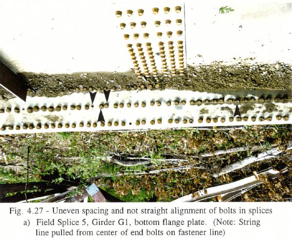
Field and shop splice bolt groups. Many hole layouts for the bolted field and shop splice connections were not drilled in accordance with the 3 inch typical longitudinal spacing detailed on the shop drawings. In addition, the longitudinal holes were not drilled in a straight line. A photograph of the bottom flange plate connection at FS5 for Girder G1 is shown in Figure 4.27a. The inside row of bolts has a string line pulled between the centers of the end bolts. Some holes along the fastener line are offset by ±1/2 inch from a straight line layout. Arrows indicate where bolt hole locations deviate significantly from the as-detailed layout.
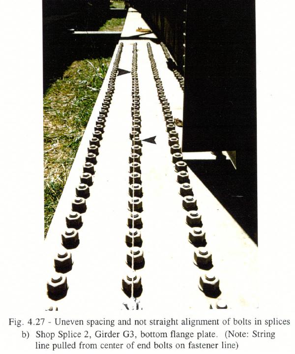
Figure 4.27b is a similar view of the bolt group for SS2 of Girder G3. The string line pulled over the bolt row directly shows longitudinal hole offsets up to ±1/2 inch from a straight alignment.
Even though these bolt hole patterns are spaced unevenly and exhibit transverse offsets from a straight alignment, it should be pointed out that all bolted splices were found to be intact after the collapse.
Back to page top
Back to WJE Report Chapter 3
WJE Table of Contents